
Jamie shares an improved methodology for dumping the firmware of an Apple AirTag.
Unlike highly locked-down (and expensive-to-brick) devices like the iPhone, AirTags provide a much gentler introduction to the extraction and reverse-engineering of Apple device firmware.
The main processor inside the AirTag is an nRF52, and its firmware is stored in on-chip flash memory. The chip has a Single Wire Debug (SWD) interface, which allows us to connect GDB on a host computer to the chip, and assume full control over execution – we can use this to read off the device’s flash memory. The SWD interface is comparable to JTAG on other microcontrollers.
Of course, it was never going to be that simple: the nRF52 has a security feature called APPROTECT, which effectively disables this debugging functionality. There is a way by which APPROTECT can be disabled, but only through a process which simultaneously wipes the memory of the device – analogous to fastboot oem unlock on an Android phone.
A bypass for this protection feature, allowing full debug control of a still-functioning device, was published by LimitedResults last year, and was first shown to work on the AirTag by stacksmashing, in this video.
We quickly bought a pack of AirTags and set about trying to reproduce this attack, but swapping the DIY microcontroller-plus-transistor setup for a ChipWhisperer-Lite, like so:

A simplified wiring diagram of our setup. Pin numbers on the AirTag are as per Colin O’Flynn’s numbering
The “Power Supply” in this diagram is makeshift, much like stacksmashing’s: we use an ESP8266 devboard programmed to receive commands over serial and toggle GPIO pins. These pins cannot source much current, so the rise time of the power supply is pretty poor (and there’s a risk of damaging the ESP8266 chip). We initially attempted to use the toggleable 3.3V power output of the ChipWhisperer to power the AirTag, but found that we would sometimes trip its overcurrent protection, resetting the ChipWhisperer at inopportune moments.
The whole process is controlled by Python on a host computer, like so:
import chipwhisperer
import serial
import os

SCOPETYPE = 'OPENADC'
PLATFORM = "NOTHING"

# You'll need to replace this if not running from a jupyter notebook
%run "jupyter/Setup_Scripts/Setup_Generic.ipynb"

scope.glitch.clk_src="clkgen"
scope.glitch.output = "enable_only"
scope.glitch.trigger_src = "ext_single"
scope.glitch.arm_timing = "before_scope"

scope.io.glitch_lp = True
scope.io.glitch_hp = True

scope.adc.samples = 1

ser = serial.Serial("/dev/tty.usbserial-0001")

while True:

# Power the AirTag off
ser.write(b'0')
# Time after trigger to glitch, in CW clock cycles.
scope.glitch.ext_offset = ???
# Length of the glitch pulse
scope.glitch.repeat = 3

# Reset the glitching module. Things break if you don't do this, I don't know why.
scope.io.glitch_lp = False
scope.io.glitch_hp = False
scope.io.glitch_lp = True
scope.io.glitch_hp = True

# Wait for the AirTag to finish powering off (it has a lot of capacitance)
time.sleep(0.5)

scope.arm()
# Power the AirTag on
ser.write(b'1')
scope.capture()
scope.get_last_trace()
time.sleep(0.1)
exit_status = os.system('openocd -f openocd.cfg -f /usr/local/share/openocd/
scripts/target/nrf52.cfg -c "init;dump_image nrf52_flash.bin 0x0 0x80000;exit"')
// 256
if exit_status == 0:
print("SUCCESS")
break
The overall flow of this process is shown as the diagram below:

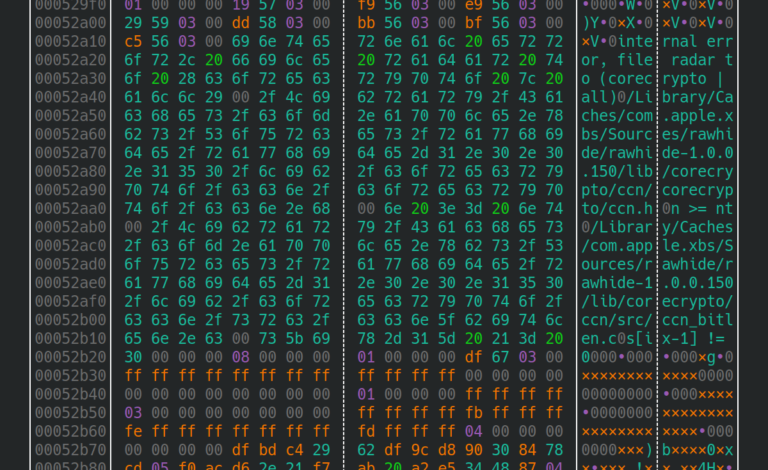
After several thousand attempts, a debug connection is successfully established, and the chip gives up its secrets!
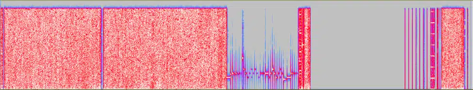
Loading the firmware dump into Audacity as 16-bit signed PCM data, we can hear the all the AirTag’s sound effects. We also get our first hint at the structure of the binary: The gap before 0x1c000 is consistent with the use of Nordic Semiconductor’s S132 SoftDevice:
Several thousand attempts!?
We were left unsatisfied by the inconsistency of this attack, and wanted a more reproducible setup. Tuning the parameters of a glitching attack is difficult, and potentially destructive: how do you systematically develop an attack, with so much uncertainty in play?
We’ll need to dive in to the specifics of the attack to see how we can improve it. After we turn on the 3V supply to the AirTag, a sequence of regulators produces a CPU voltage called Vcore, which is somewhere in the region of 0.9V. Let’s inspect the first few milliseconds of the startup process – 3V is displayed in pink, Vcore in yellow – note the different axis scales on the right-hand side:
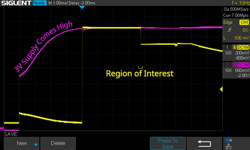
4ms after the 3V supply first appears, Vcore comes to 1.32V. This sharp rise is what our oscilloscope is currently set to trigger on. After another 3.77ms, it drops to 1.1V. The moment right before this drop is what we’re interested in glitching. Let’s zoom in on that region:
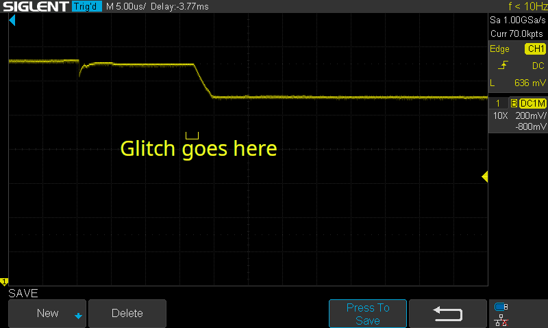
Imagine we wait for the rise of Vcore, sleep for a fixed period, then perform the glitch. This sounds good in theory, but look at what happens to the above signal when we overlay multiple startup attempts:
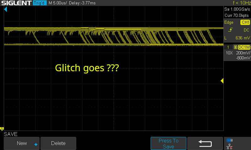
The moment we want to glitch is roughly 1μs wide, but the time from Vcore going high to Vcore dropping to 1.1V fluctuates by almost 100μs! It’s definitely possible to perform the glitch this way (as we saw above), but it requires a lot of luck, which means a lot of attempts. If you don’t know that your glitch parameters are correct, how many attempts do you sit through before you tweak something?
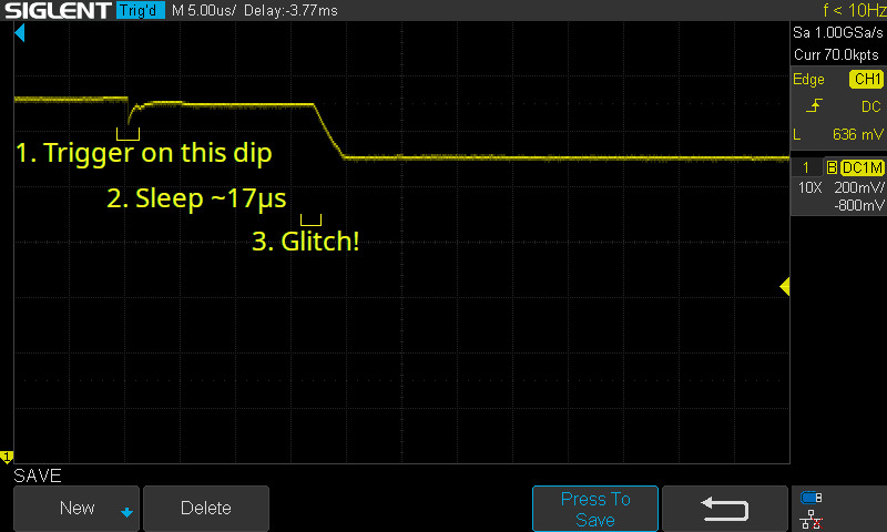
A better approach
Instead of timing our glitch with this [~3700±100]μs delay, it would be ideal to time relative to the small dip in Vcore, which occurs just 17μs before the glitch target.
This is more involved than triggering on the rising edge of the 3V rail. In that case, we could simply connect the 3V line to a microcontroller’s logic input, and request an interrupt when it goes high. In this case, we need analog circuitry to detect and quickly react to the small dip – something the ChipWhisperer Lite cannot do.
We do have something which can perform this triggering though: the oscilloscope we’ve been using to inspect the signal! By connecting the Trigger Out connector of a scope to the Trigger input of the ChipWhisperer, we can use the scope’s powerful signal-processing capabilities to time our attack.
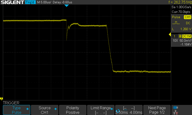
This screenshot shows a suitable trigger configuration: the scope is set to trigger at the end on a positive pulse above 1.260V, with a length in the range 3.5ms-4ms. Note that we’ve zoomed in on the Y-axis, increasing the vertical resolution of the signal which reaches the trigger circuit.
We can overlay multiple startups again to confirm that we aren’t capturing any other moments:
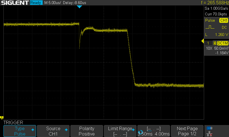
Perfect – a highly consistent signal each time.
Our attack flow now looks something like this:

We successfully carried out the glitching attack with this setup: once a good ext_offset value was chosen, it worked on the first attempt, repeatably.
Conclusion
We hope that the consistency afforded by this oscilloscope-triggering approach can be helpful for others carrying out similar attacks on other hardware platforms, and potentially even other chips. Hardware fault injection is an exciting field, and we’re looking forward to seeing future techniques develop and become more widespread.